Industrial PC & Panel PC Chassis
Housings built around your board: industrial PC cases, panel PC front bezels and rear housings, fanless box computers and DIN-rail enclosures — cut to the interface drawing so connectors, LEDs, fans and mounting holes land where the PCB expects them.
Built Around the Board, Not Around a Stock Box
An industrial computer chassis is a mechanical agreement with a PCB. Stand-off positions, connector apertures, card-slot alignment and airflow all have to match a layout the electronics team has already committed to. Measured against a catalogue box, those details usually fail.
We build to your board drawing and your mounting concept: stand-off pattern, I/O cut-outs, retention for add-in cards, fan and filter provision, and the front bezel geometry for a panel mount. Where the drawing leaves a detail open, we raise it at review rather than resolving it quietly.
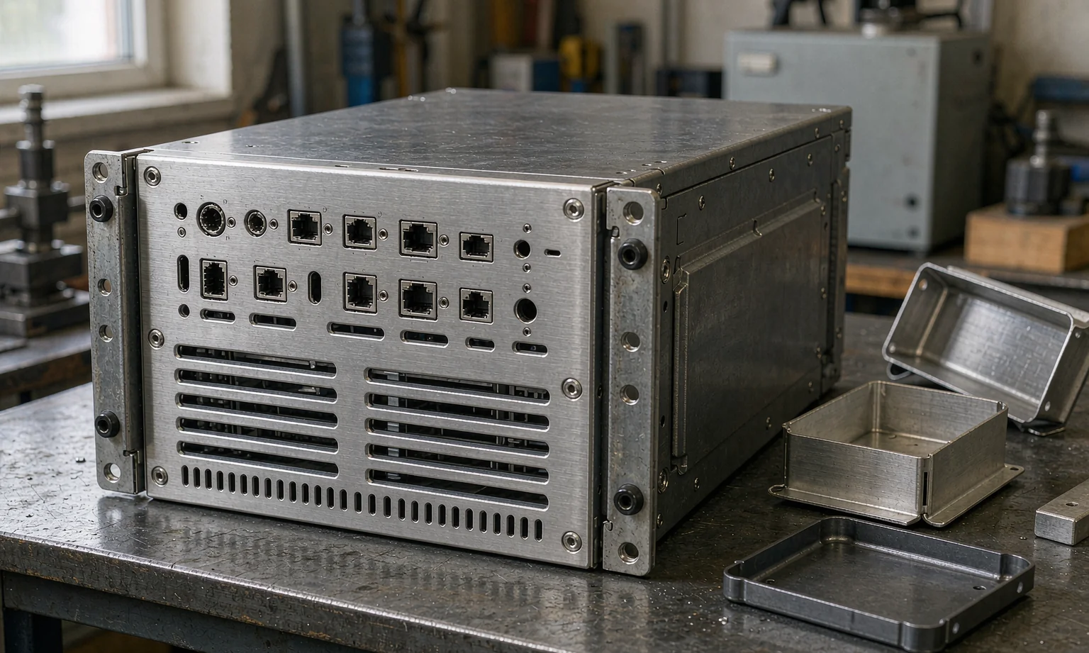
Closer Look at This Enclosure Type
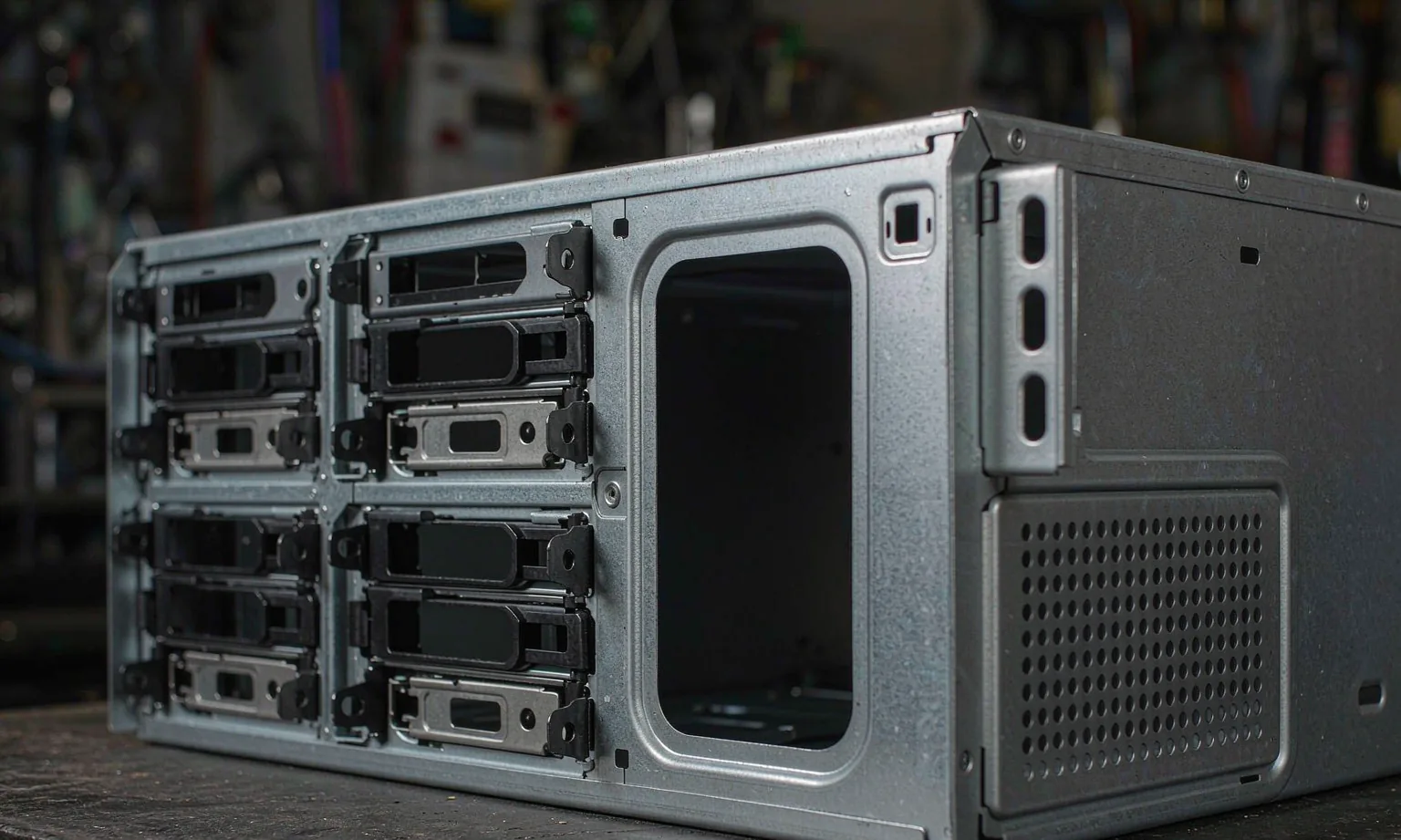
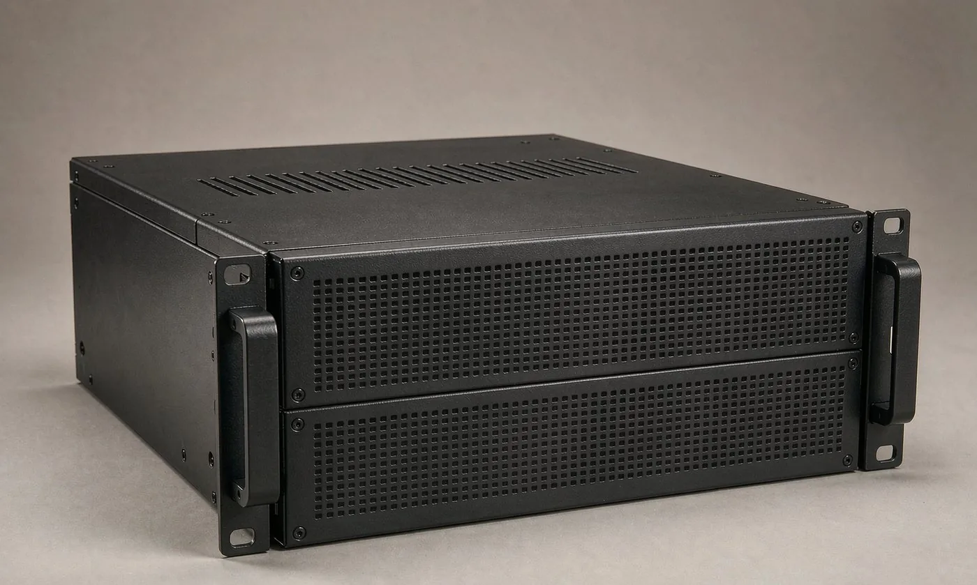
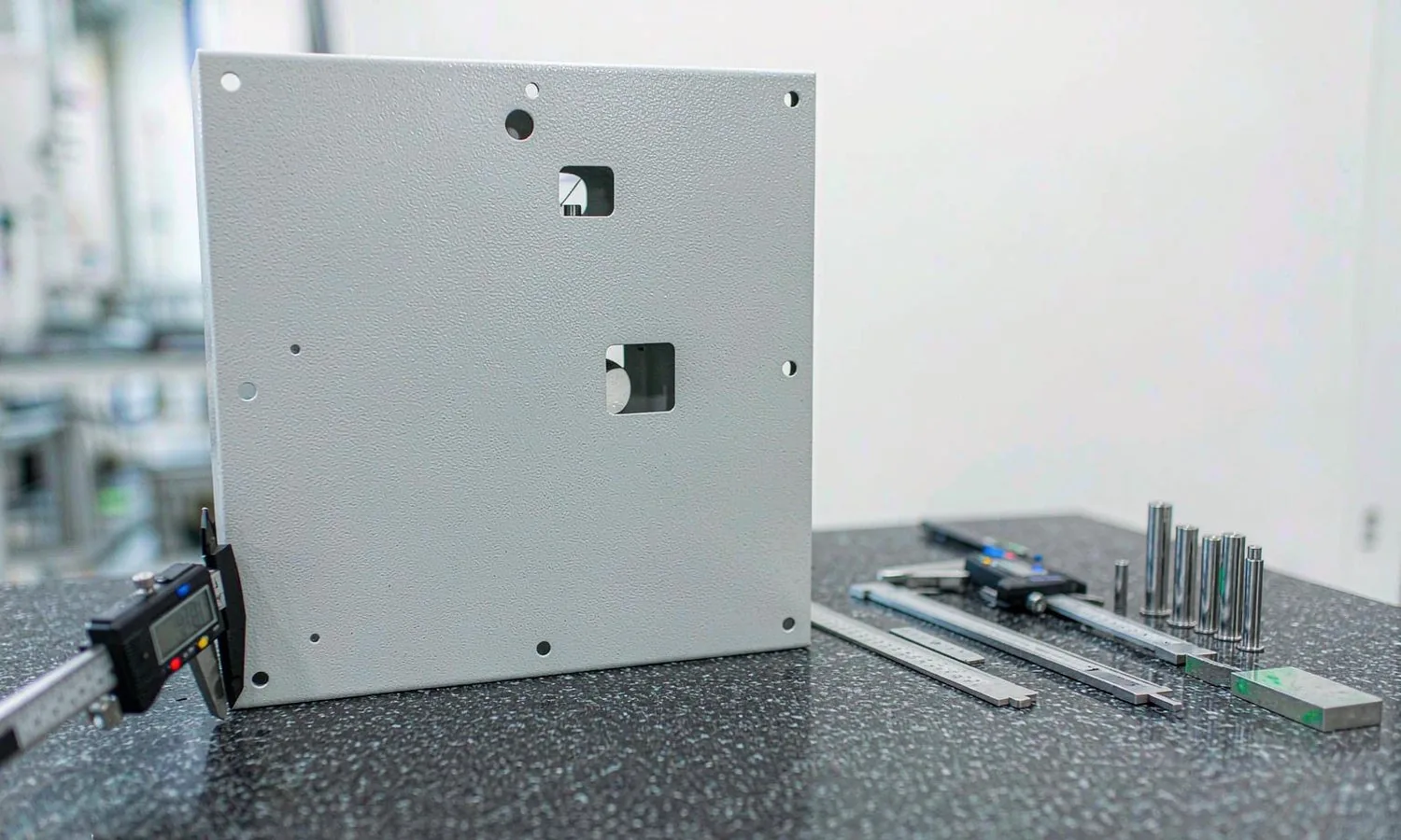
Representative photographs of the construction, interfaces and installation context for this product family.
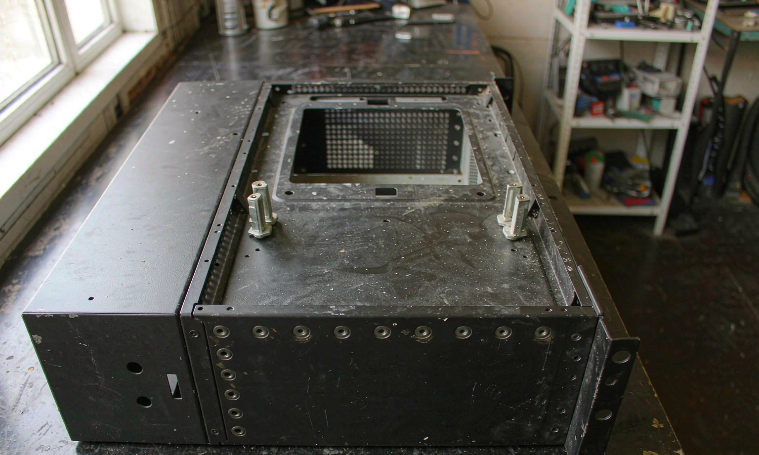
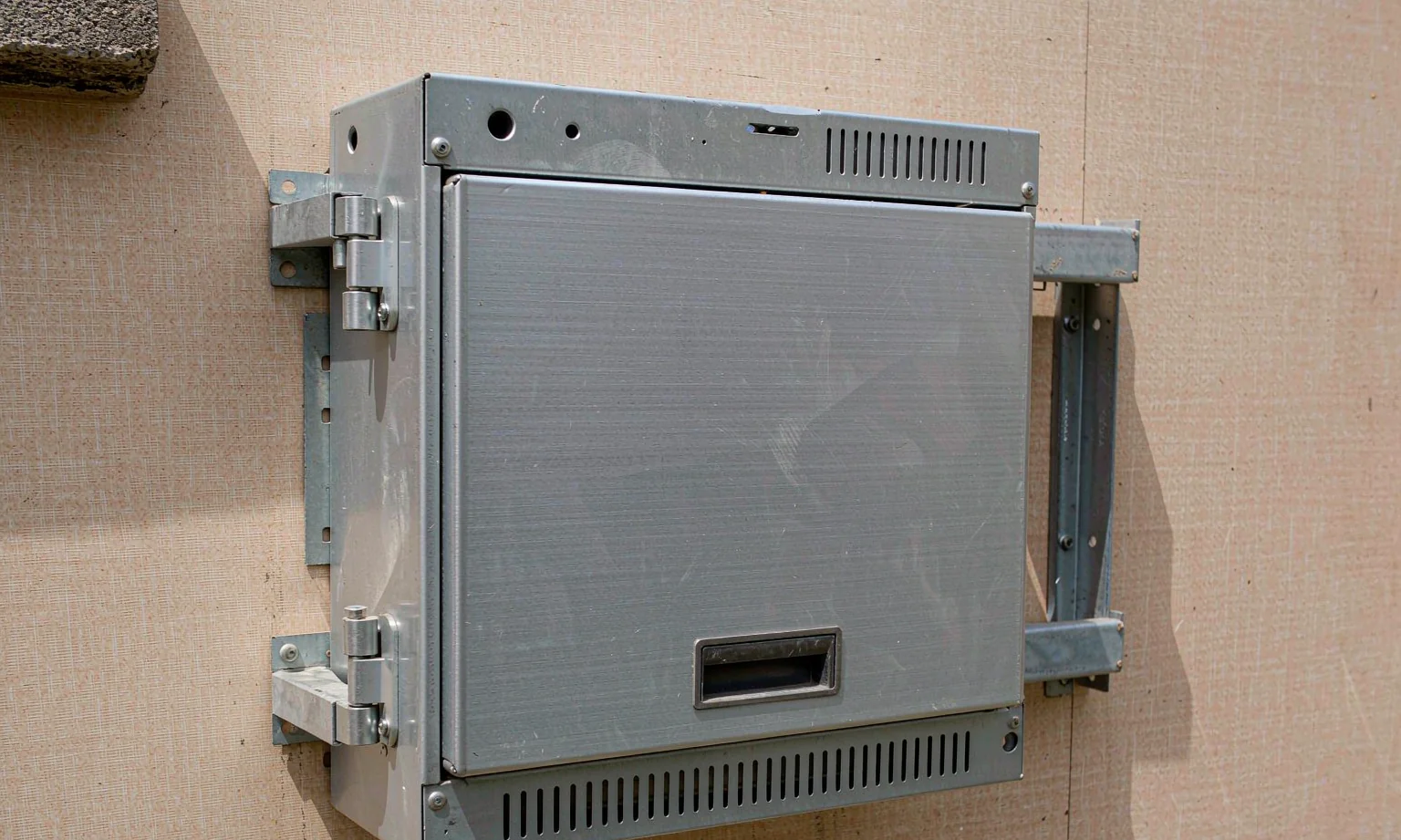
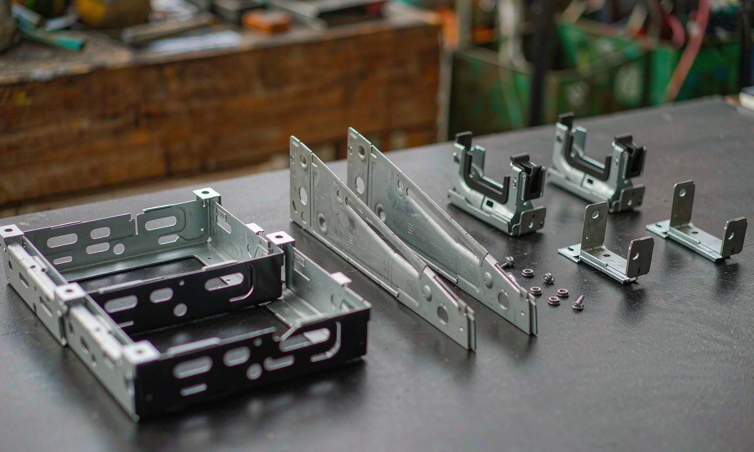
Specifications at a Glance
| Parameter | Typical Specification |
|---|---|
| Typical products | Industrial PC chassis, panel PC bezel and rear housing, fanless box PC, DIN-rail enclosure, wall-mount computer housing |
| Height range | 1U to 6U rack chassis; box and panel housings from 40 mm to 250 mm deep |
| Materials | SPCC 0.8-2.0 mm, SECC/SGCC, aluminum 5052 and 6061 for heat dissipation and weight |
| Interfaces | Connector apertures, card slots, LED and button bores cut to the board drawing |
| Mounting | Motherboard stand-offs, card retainers, VESA patterns, DIN-rail clips, wall brackets |
| Thermal | Vent patterns, fan apertures and filter frames; heat-sink interfaces on aluminum housings |
| EMC provision | Conductive gasket channels, Earth studs and panel-to-panel bonding points |
| Tolerance | ±0.15 mm on connector and stand-off positions, ±0.1 mm on critical fits |
| Finish | Powder coat, anodized aluminum, zinc plating, or brushed stainless front panels |
| Configuration | Flat kit, or part-assembled chassis with inserts and hardware fitted |
The parameters above are representative of typical projects in this category. Your drawing defines the final specification, and every quotation states the scope it covers.
Popular Configurations We Manufacture
Every size and option is customised to your drawing. Use a configuration below as a starting point for your enquiry.
1U to 6U Industrial PC Chassis
Rack-mount cases with card retention, airflow and cable management.
| Height | 1U to 6U |
| Features | Card brackets, fan wall, cable tie points |
| Access | Top or side cover, front bezel options |
Panel PC Bezels and Housings
Front bezels and rear housings that carry a display and a PC board.
| Bezel | Cut to the display outline and touch window |
| Interface | Connector apertures on the underside or rear |
| Mounting | Panel, VESA or arm mounting provision |
Fanless Box and DIN-Rail Enclosures
Sealed enclosures that dissipate heat through the case rather than a fan.
| Material | Aluminum 6061 for heat spreading |
| Sealing | Sealed lid with gasket, no vent openings |
| Mounting | DIN rail, wall bracket or desk feet |
Materials, Finishes & Customisation
Chassis material
| Cold-rolled SPCC | 0.8-1.5 mm — coated chassis where cost and formability matter |
| Aluminum 5052 / 6061 | 1.0-3.0 mm — lighter cases and heat-spreading bodies |
| Galvanized SGCC / SECC | 0.8-1.2 mm — internal structure and card brackets |
| Stainless SUS304 | 1.0-1.5 mm — front panels and washdown operator stations |
Thermal and EMC
| Ventilation | Laser-cut vent patterns sized to the airflow you specify |
| Filters | Removable filter frames on fan apertures |
| EMC | Conductive gasket channels and bonding points where shielding is required |
| Heat sinking | Aluminum bodies with defined mounting flats for direct contact |
Assembly and finish
| Finish | Powder coat in any RAL; anodizing for aluminum front panels |
| Inserts | PEM nuts, studs and stand-offs pressed to specification |
| Delivery | Flat kit, sub-assembly, or chassis built with hardware fitted |
How This Moves Through the Workshop
Your board and mechanical drawings are reviewed together for stand-off patterns, connector clearance and airflow paths. Flat patterns are laser cut with all apertures and stand-off holes in one program, parts are formed, and machined features such as countersinks and slots are added. Chassis are then coated, inserts are pressed, and a sample unit is trial-assembled against a board or a pin gauge before the batch is released.
- Drawing review with DFM feedback before production release
- Fiber laser cutting of the complete flat pattern in one set-up
- CNC press-brake forming, welding and grinding
- Coating applied before gaskets, hardware and glass are fitted
- First-article and sample inspection recorded for each batch
Common Questions
Yes, provided the drawing shows the board outline, stand-off positions, connector positions and component heights. Where a detail is unclear we ask at review rather than assuming. If you can send a sample board or a 3D model, the fit becomes much easier to guarantee.
Laser cutting is the standard route, because apertures and stand-off holes come out of the same program, so the relationship between the vent field and the mounting pattern is fixed. Punching is an option where the vent shape is a standard tool and quantities are high.
Yes. Panels and brackets can ship flat as a kit with inserts already pressed, or as a part-assembled chassis with the frame riveted, so your assembly line only has to fit the board and close the lid.
Where shielding is part of the requirement we provide conductive gasket channels, bonding points between panels and an Earth stud, and keep coating off the surfaces that must make electrical contact. Compliance testing of the finished computer remains with you.
Send Us Your Drawing
Tell us what you need made, the environment it works in and the quantity — we will return engineering feedback and a quotation, typically within 24 hours on working days.