Robot Bases, Machine Guarding & Automation Frames
The fabricated steel an automation cell sits on and works behind — robot pedestals, guarding panels, gantry and conveyor frames, fixture plates and AGV bodies — welded and machined so the mounting faces stay flat and square for the equipment that bolts onto them.
Structure Before Electronics
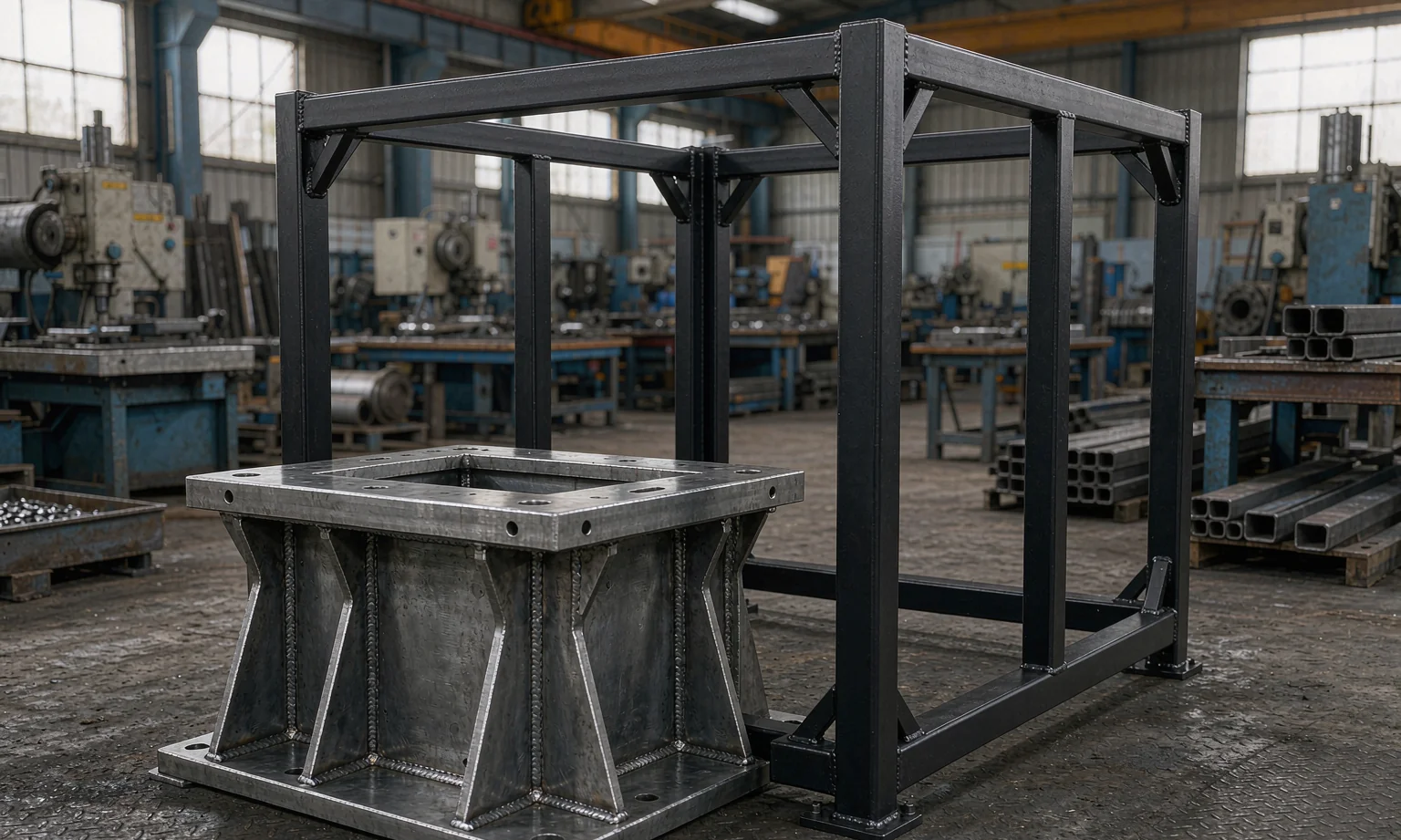
In an automation cell the electronics get the attention, but the accuracy often lives in the steel. A robot pedestal that is not flat will tilt the arm; a fixture plate that is not square will put every part a little out of position; a gantry frame that twists during welding will never line up again. Welding moves metal, and the only reliable way to a true face is to control the weld sequence and then machine the interface.
We fabricate pedestals, guarding, frames and fixture plates to your drawing, control distortion through jigging and weld sequence, and machine the critical faces after welding when your tolerance demands it. The drives, servos, gearboxes, controls and safety function remain with you — we make the structure and state that boundary on the quotation.
Closer Look at This Enclosure Type
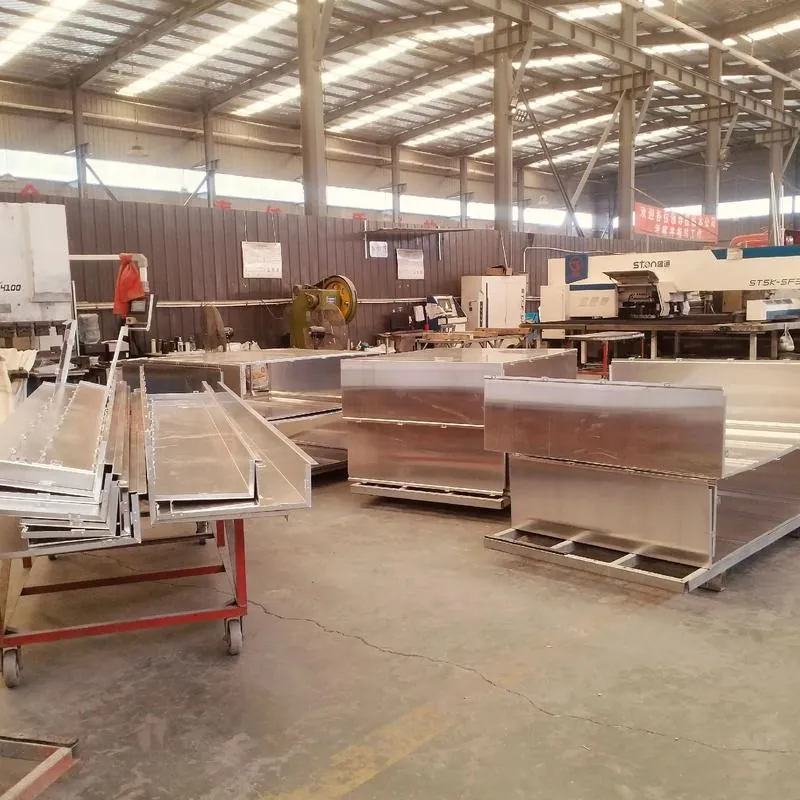
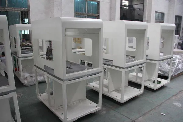
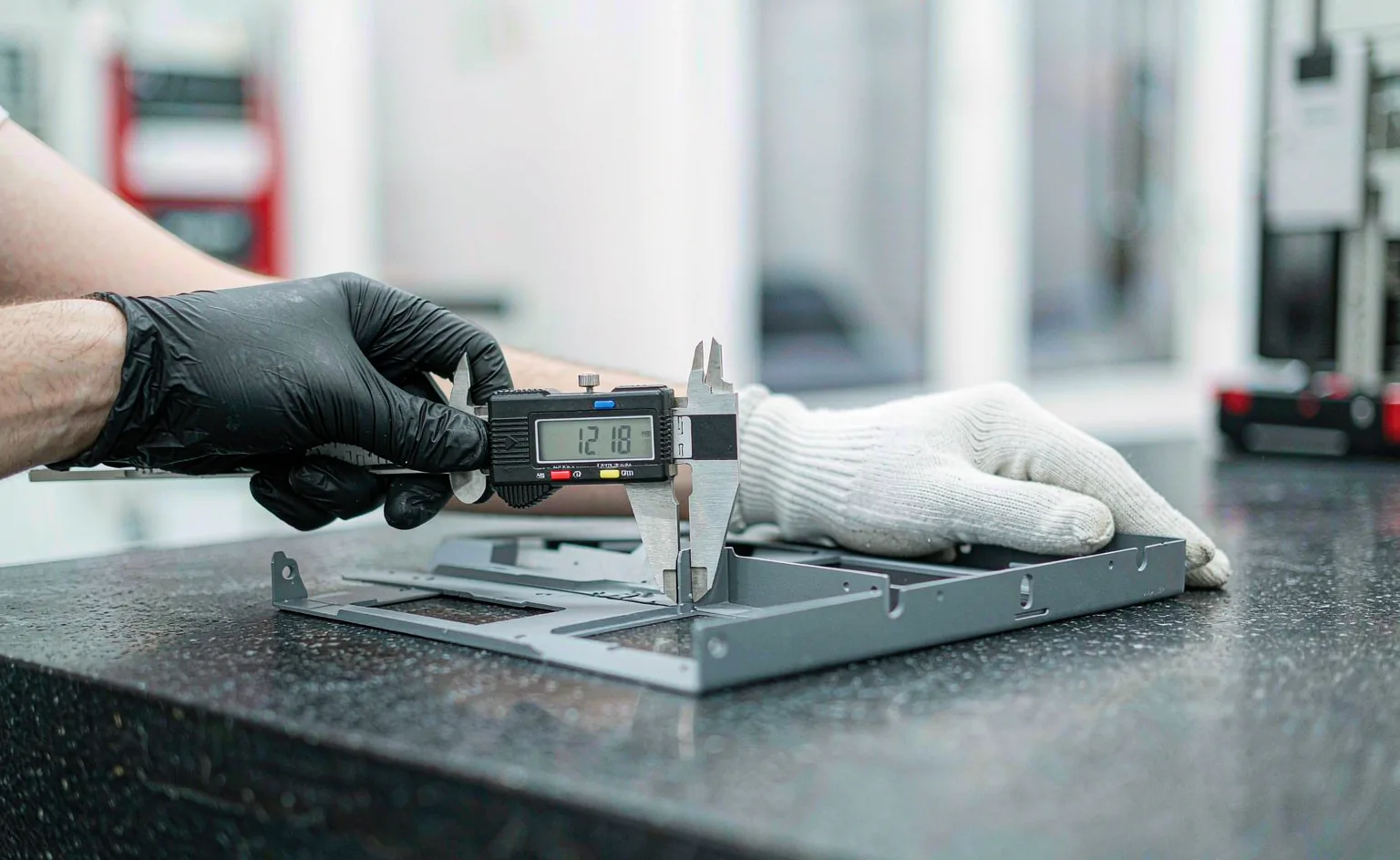
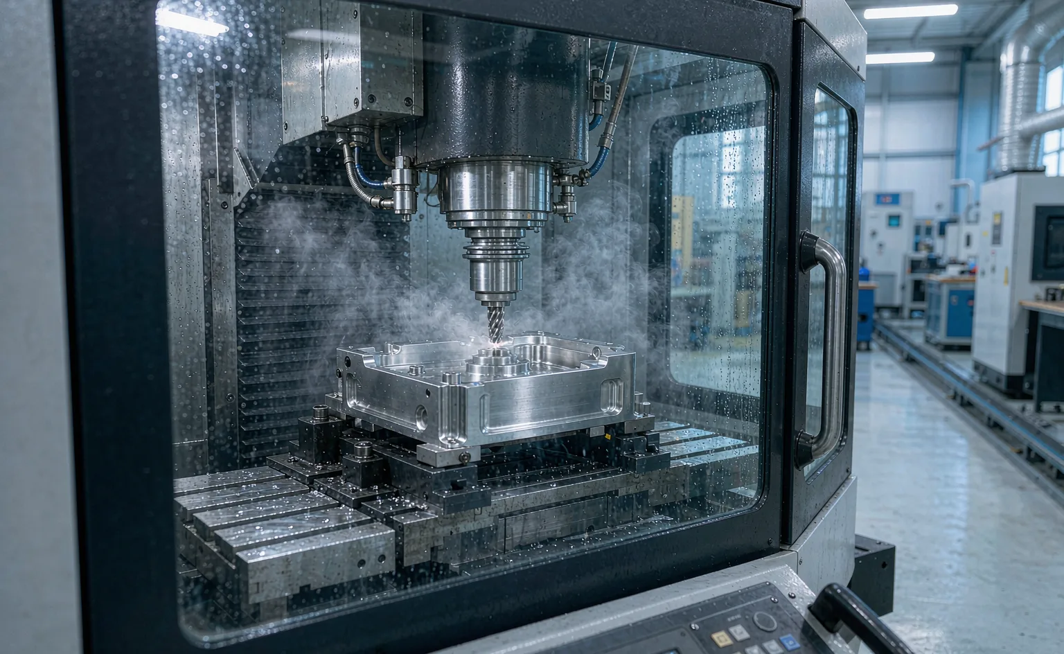
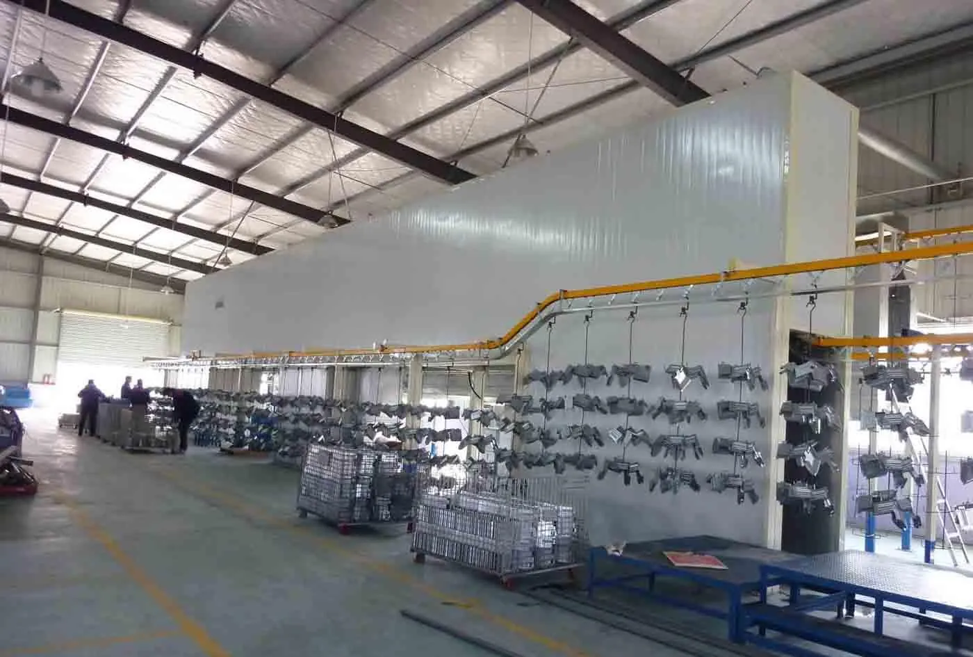
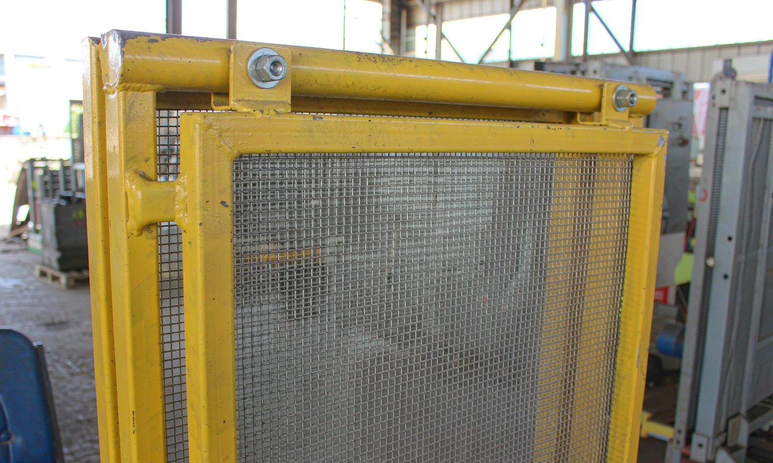
Representative photographs of the construction, interfaces and installation context for this product family.
Specifications at a Glance
| Parameter | Typical Specification |
|---|---|
| Typical parts | Robot pedestals and bases, machine guarding and fence panels, gantry and conveyor frames, fixture and mounting plates, AGV and AMR bodies, machine bases, cable trays and covers |
| Materials | Structural and sheet steel SPCC / Q235 / Q355, stainless SUS304 for washdown cells, aluminium 5052 / 6061 where weight matters |
| Thickness range | Guarding and panels 1.5–3.0 mm; frames and pedestals 3.0–8.0 mm; fixture plates up to 8.0 mm before machining |
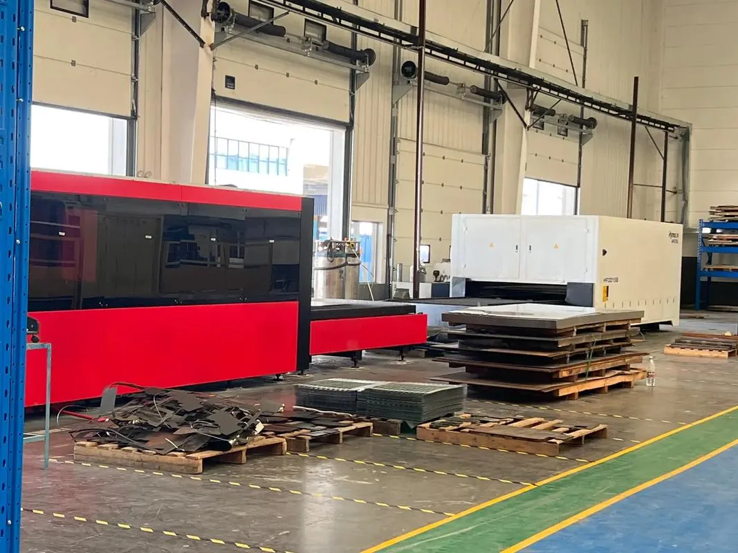
| Cutting & forming | Fiber laser cutting up to 3000 × 1500 mm, press-brake forming, tube and profile cutting for frame members |
| Welding | MIG and TIG welding with jigs and a fixed sequence to control distortion; grinding and dressing where specified |
| Secondary machining | Critical faces milled, slots and keyways cut, and bores finished after welding when flatness or squareness demands it |
| Tolerance | Frame squareness and mounting-face flatness to the value on your drawing; machined interfaces tighter than as-welded |
| Finishes | Powder coating in any RAL, machine-grey finishes, or primed and left for your own top coat |
| Interfaces | Tapped holes, pressed inserts, slotted mounting patterns and alignment pins produced to drawing |
| Inspection | Dimensional and squareness checks recorded per batch before coating and again before dispatch |
The parameters above are representative of typical projects in this category. Your drawing defines the final specification, and every quotation states the scope it covers.
Popular Configurations We Manufacture
Every size and option is customised to your drawing. Use a configuration below as a starting point for your enquiry.
Robot Pedestals & Machine Bases
The base that a robot or machine bolts to, kept flat and square on the mounting face.
| Material | Steel 3.0–8.0 mm, or aluminium where weight is critical |
| Faces | Critical mounting face machined after welding |
| Interfaces | Hole patterns and alignment features to your robot drawing |
Machine Guarding & Fencing
Panels and frames that enclose a cell and keep operators clear of moving parts.
| Material | Steel 1.5–3.0 mm, stainless for washdown cells |
| Build-up | Panel and mesh infill prepared to your specification |
| Finish | Powder coated in the colour your site standard uses |
Gantry, Conveyor & Fixture Structures
Welded frames and fixture plates that hold production equipment in position.
| Material | Steel sections and plate up to 8.0 mm |
| Welding | Jigged sequence to limit twist and bow |
| Machining | Slots, bores and faces cut after welding where required |
Materials, Finishes & Customisation
Material choice
| Structural steel Q235 / Q355 | 3.0–8.0 mm — pedestals, frames and machine bases |
| Cold-rolled SPCC | 1.5–3.0 mm — guarding panels, covers and enclosures |
| Aluminium 5052 / 6061 | 2.0–8.0 mm — moving parts where weight and inertia matter |
Distortion & accuracy
| Jigging | Parts held in fixtures during welding to hold geometry |
| Weld sequence | Balanced sequence and tacking used to limit heat input and bow |
| Post-weld machining | Critical faces milled and bores finished only after welding |
Finishes & interfaces
| Powder coating | Full RAL range over pre-treatment for guarding and visible frames |
| Machined faces | Left bare or lightly protected to keep mounting accuracy |
| Hardware | Tapped holes, pressed inserts and alignment pins fitted to drawing |
How This Product Moves Through the Workshop
Frame and pedestal drawings are reviewed for welding access, machining allowance and interface tolerance before cutting. Members are laser cut or profile cut, formed where needed, then welded in jigs to a controlled sequence so the geometry holds. After welding, parts that carry an accuracy requirement are set up again for milling, slotting and boring of the critical faces. Dimensions and squareness are recorded, surfaces are coated where the drawing calls for it, and hardware is fitted before packing. Fabrication and machining are handled in one route so the person cutting the metal and the person truing it are working from the same drawing.
- Drawing review with DFM feedback before production release
- Fiber laser cutting of the complete flat pattern in one set-up
- CNC press-brake forming, welding and grinding
- Coating applied before gaskets, hardware and glass are fitted
- First-article and sample inspection recorded for each batch
Common Questions About This Product
No. We fabricate and machine the structure — pedestals, bases, guarding, frames and fixture plates. Robot selection and integration, drives, servos, gearboxes, controls and the electrical package stay with you. We make the metal so your integrator has a true, square base to build on, and that boundary is stated on every quotation.
Yes — this is exactly why we machine after welding. Where your drawing states a flatness or squareness tolerance on a mounting face, we weld first, then set the part up and mill or bore the critical surface so the tolerance is achieved on the finished part rather than on the raw plate.
As-welded frames are built square to the value stated on your drawing, typically ±0.5 mm over the frame envelope, and machined interfaces are held to ±0.1 mm where the drawing calls for it. Tell us which faces actually matter and we will concentrate the accuracy there rather than over-tolerancing the whole part.
Distortion is managed before the first bead: balanced weld sequence, correct tacking, jigs that hold geometry during welding, and allowance for movement. Where a frame is long or thin-walled we may recommend a stress-relief or a re-machining step, and we will raise that during DFM review.
We build to print. Send existing drawings, or a 3D model plus a drawing showing the critical interfaces, and we will review manufacturability and return questions before cutting. Where only a model exists we can work from it once the tolerance and finish requirements are agreed in writing.
Guides for This Application
How to Control Welding Distortion in Sheet Metal
Why sheet metal weldments distort, and practical controls: joint design, weld sequence, tacking, heat input, f
Read guideSheet Metal Tolerances Explained: What Is Realistic
Achievable sheet metal tolerances for laser cutting, bending and welding, how tolerance stacks up, and how to
Read guideSheet Metal Design Rules: A Practical DFM Guide for Enclosures
The design rules that decide whether your enclosure is cheap or expensive: hole-to-bend distance, bend relief,
Read guideSend Us Your Drawing
Tell us the enclosure you need, the environment it works in and the quantity — we will return engineering feedback and a quotation, typically within 24 hours on working days.