CNC Press Brake Bending Services
Forming is where a good flat pattern becomes a square, dimensionally stable part — or a scrap pile. We set up tooling, bend sequence and springback compensation per job, not per operator habit.
How We Control the Bend
Bending errors rarely show up on the brake. They show up at assembly, when a cabinet door will not sit flat or a bracket will not line up with its mating holes. The causes are predictable: bend allowance taken from the wrong K-factor, a bend sequence that traps a flange, or springback that was never compensated for in the material actually being used.
Every formed part is set up against the drawing: tooling radius, V-opening, bend deduction and back-gauge positions are calculated for the specific material and thickness, and the first part is measured before the batch continues. Angle-critical assemblies are formed in a sequence that avoids re-gripping a finished face.
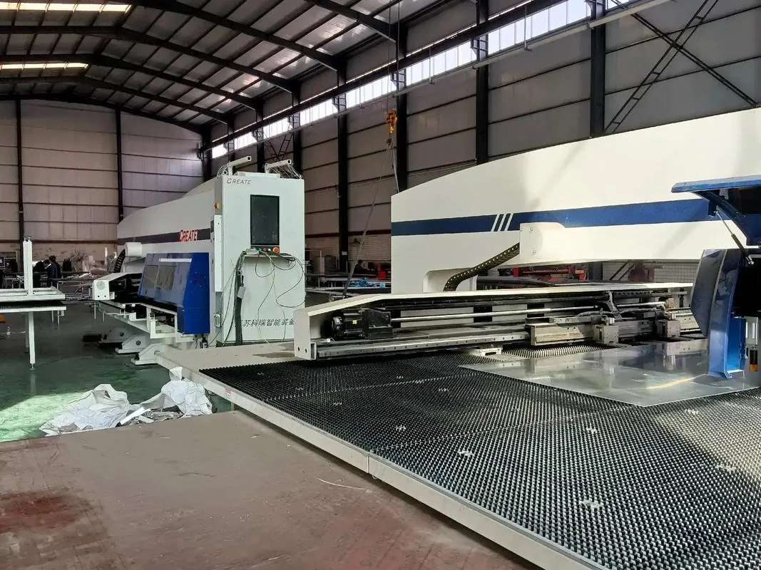
A Closer Look at This Capability
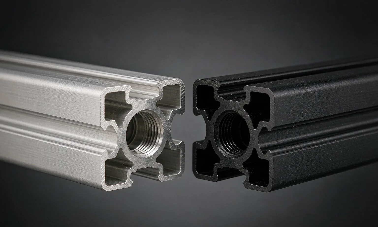
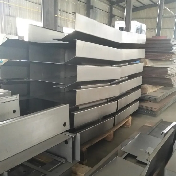
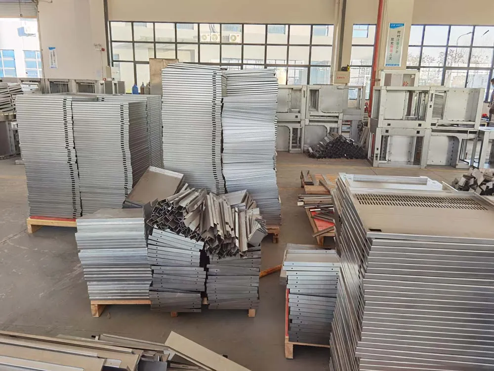
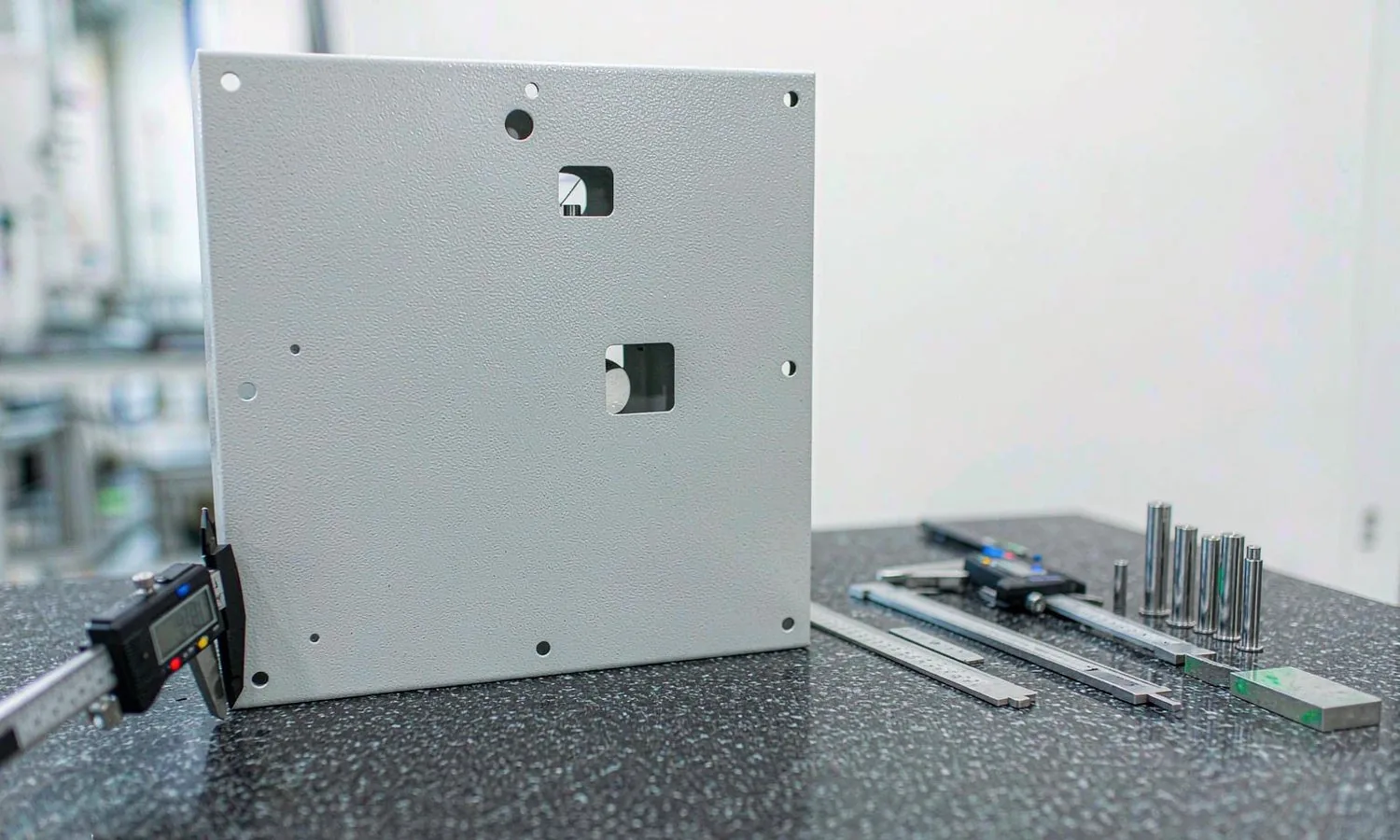
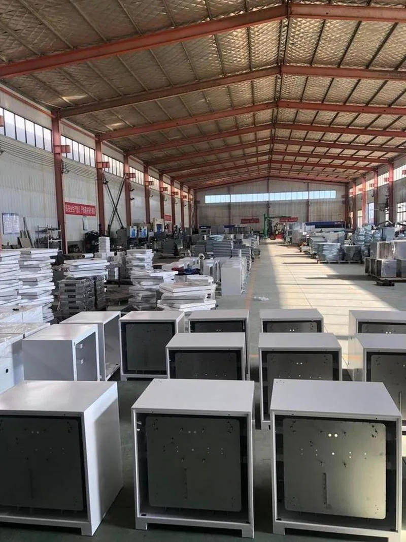
Representative photographs of the equipment, the process and the parts produced.
Specifications at a Glance
| Parameter | Typical Specification |
|---|---|
| Materials formed | Cold-rolled steel, galvanized steel, stainless steel 304 / 316L, aluminum, and pre-coated sheet |
| Thickness range | 0.5-8.0 mm depending on material and bend radius |
| Maximum bend length | Up to 3000 mm per bend |
| Angle tolerance | Typically +/-0.5 deg on normal parts, tighter verified against the drawing on critical assemblies |
| Bend radius | Matched to material and tooling; minimum inside radius confirmed during DFM review |
| Tooling | Standard V-dies plus special tooling for hemming, radius forming and box bending |
| Springback | Compensated per material batch and thickness rather than left to operator judgement |
| Bend sequence | Planned so finished faces are not re-gripped, and trapped flanges are formed in the correct order |
The parameters above are representative of typical work in this category. Your drawing defines the final specification, and every quotation states the scope it covers.
What We Do in This Area
Every job is customised to your drawing. Use these categories as a starting point for your enquiry.
Cabinet and Enclosure Bodies
Multi-bend bodies with double flanges, gasket channels and door openings formed in a controlled sequence.
| Thickness | 0.8-3.0 mm |
| Typical length | Up to 2000 mm |
| Key control | Squareness and diagonal |
Brackets, Angles and Supports
Small formed parts where angle accuracy and hole alignment matter more than size.
| Thickness | 0.5-6.0 mm |
| Batch size | From 1 piece |
| Key control | Angle and hole position |
Radius, Hem and Box Bends
Radius bends, hemmed edges, J-channels and box forms using matched tooling.
| Tooling | Standard plus special |
| Hemming | Available |
| Key control | Radius consistency |
Capability, Tolerances & Documentation
Forming capability
| Max bend length | 3000 mm |
| Thickness | 0.5-8.0 mm |
| Angle tolerance | +/-0.5 deg |
| Radius | Matched to material |
Tooling available
| V-dies | Standard range |
| Special tooling | Hem, radius, box |
| Back gauge | CNC controlled |
| Compensation | Per material batch |
Quality control
| First article | Measured before batch |
| In-process | Sampled checks |
| Angles | Protractor and gauge |
| Report | On request |
Where This Fits in the Production Route
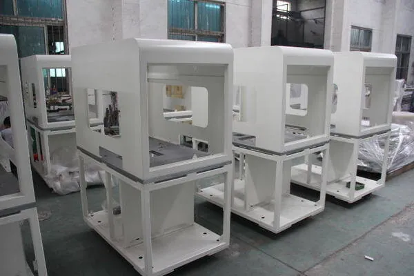
Forming starts with the flat pattern and the drawing, not with the machine. Tooling, V-opening, bend deduction and sequence are planned first, then the first part is formed and measured. If an angle or a flange length is out of tolerance, it is corrected at setup rather than sorted out later at assembly. Parts that will be welded are formed to the same reference dimensions as parts that will be bolted, so the two fit together the first time.
- Drawing review with DFM feedback before production release
- Fiber laser cutting of the complete flat pattern in one set-up
- CNC press-brake forming, welding and grinding
- Coating applied before gaskets, hardware and glass are fitted
- First-article and sample inspection recorded for each batch
Common Questions
Up to 3000 mm per bend. Longer profiles are formed in sections or designed as welded assemblies.
We form carbon steel from 0.5 mm up to 8.0 mm, with the achievable radius and bend length depending on the material and tooling. Thickness and radius are confirmed at quotation stage.
Springback is compensated per material batch and thickness during setup, and the first part is measured. For angle-critical parts we plan the sequence so the part is not re-gripped on a finished face.
We work from your flat pattern or generate one from your 3D model. If bend allowance or K-factor on your drawing differs from ours, we raise it during DFM review before cutting.
Yes, with matched tooling radii and care at the bend line. Where a coating is prone to cracking at tight radii, we recommend a larger inside radius or cut-and-form detailing.
Forming normally happens before coating, since bending a coated surface risks cracking at the radius. Where touch-up is needed after forming, we handle it before final packing.
Send Us Your Drawing
Tell us what you need made, the environment it works in and the quantity — we will return engineering feedback and a quotation, typically within 24 hours on working days.