Sheet Metal Design Rules: A Practical DFM Guide for Enclosures
DFM Anjue Metal | Engineering | 13 min read | Updated Oct 8, 2026
Two enclosures can do the same job and differ by 40% in price, purely because of how the drawing was laid out. Design for manufacturability is not an academic exercise - it is the difference between a part that runs cleanly on a press brake and one that needs rework at every station. This guide collects the rules we apply every day when we review customer drawings.
- Why DFM Decides Your Price, Not Your Volume
- Start With Thickness, Not With Shape
- Bend Rules That Prevent Rework
- Bend Relief, Tabs and Corners
- Grain Direction and Material Anisotropy
- Holes, Cutouts and Edge Details
- Design for Assembly, Not Just for Cutting
- What a Factory DFM Review Should Return to You
- Our Baseline Capability
Why DFM Decides Your Price, Not Your Volume
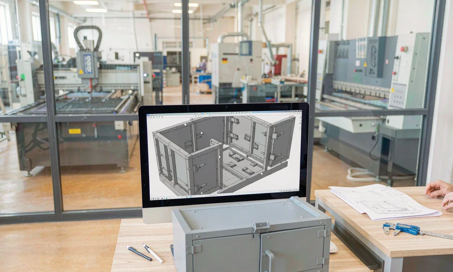
Most buyers assume price comes from quantity. Volume matters, but for custom enclosures the dominant cost driver is how many operations the part needs and how risky each one is. A part that needs four setups instead of two, or that has a bend running through a hole pattern, costs more at any quantity - because cost is built at the machine, not negotiated at the quotation.
The rules below are the ones with the biggest price impact, ordered from most to least consequential.
Start With Thickness, Not With Shape
Thickness sets everything downstream: bend radius, tooling, hardware, weld strategy and rigidity. Getting it right at the sketch stage avoids redesign later.
| Thickness | Typical use | What it gives you |
|---|---|---|
| 0.8 - 1.0 mm | Small electronic housings, cover plates, brackets | Light, cheap, needs stiffening flanges |
| 1.2 - 1.5 mm | Rack panels, control boxes, HMI enclosures | The workhorse range for indoor cabinetry |
| 2.0 - 3.0 mm | Outdoor cabinets, structural brackets, machine guards | Good rigidity without heavy welding |
| 4.0 - 6.0 mm | Base plates, heavy brackets, chassis rails | Structural; bending needs generous radii |
| 8.0 mm | Heavy machined-and-formed parts | At the practical limit of normal press brake tooling |
A useful sanity rule for panels: the unsupported span of a flat panel should stay under roughly 100 times the thickness before you add a flange, rib or stiffening groove. A 2 mm door on a 600 mm wide cabinet will drum and oil-can unless it is flanged on all four sides or has a formed stiffener.
Bend Rules That Prevent Rework
Minimum flange length
A bend needs enough flange for the press brake punch and die to grip. If the flange is too short, the part either cannot be formed or is formed with a distorted edge.
- Minimum flange length is roughly 4 x thickness plus the bend radius for standard air bending.
- The practical minimum we recommend to designers is 6 mm on 1.5 mm sheet, scaled up with thickness.
- If you need a shorter flange, the alternative is a different tooling setup, a jogged bend, or moving to a welded corner.
Minimum bend radius
Inner bend radius should never be smaller than the material thickness for mild steel, and never smaller than about 1 x thickness for aluminium if you want to avoid cracking. Aluminium 5052 will tolerate a tight radius; 6061-T6 will crack and should be formed in the O or T4 condition, or bent with a larger radius.
Hole-to-bend distance
This is the single most common DFM error we see.
- Minimum distance from a hole edge to the start of a bend: 2.5 x thickness plus the bend radius (3 x thickness for safety).
- Holes closer than that will distort into an oval during forming, and any tapped hole will no longer accept a fastener cleanly.
- If a hole must sit close to a bend, the fix is to move it, reduce the hole, or design the hole after forming.
Bend Relief, Tabs and Corners
Bend relief
Any time a bend terminates inside a flat face, it needs a relief notch. Without it, the material tears at the end of the bend line. Relief width should be at least the material thickness, and depth at least the bend radius plus thickness.
- Standard relief: width = 1 x thickness, depth = bend radius + thickness.
- For high-stress parts or thick sheet, use width = 1.5 x thickness.
Tabs and slots
Tab-and-slot self-locating joints are how good enclosures assemble themselves. Rules that keep them working:
- Tab width: at least 2 x thickness, ideally 3 x thickness.
- Slot should be laser-cut about 0.1 - 0.15 mm larger than the tab for a snug fit that still assembles by hand.
- Tabs longer than about 20 mm should be tapered or relieved, otherwise they bind.
Corner clearance
When two bends meet at a corner, the flanges collide unless you cut a clearance notch. Plan the corner as a notch in the flat pattern rather than expecting the press brake to solve it.
Grain Direction and Material Anisotropy
Rolled sheet has a grain direction. Bending across the grain gives a cleaner result; bending parallel to the grain on tight radii increases the risk of cracking, and the risk is much higher in aluminium than in steel.
- If a part has bends in two directions, you cannot avoid one set being along the grain - so keep the tightest bends across the grain.
- For cosmetic parts, keep bend lines consistent so the visible texture is uniform across a batch.
- Specify grain direction on the drawing only when it matters; unnecessarily tight grain specifications add material cost.
Holes, Cutouts and Edge Details
| Feature | Rule of thumb | Consequence if ignored |
|---|---|---|
| Round hole diameter | >= 1 x thickness (laser); >= 1.2 x thickness for punching | Rough edge, dross, punch breakage |
| Slot width | >= 1.2 x thickness | Distortion, short tool life |
| Minimum internal corner radius | >= 0.5 x thickness for laser | Sharp corners crack under load |
| Distance from hole to part edge | >= 2 x thickness | Edge bulge, tearing on forming |
| Embossed or countersunk hole | Requires forming tooling; check flat pattern | Geometry shifts after forming |
| Louvre / vent | Keep pitch and width consistent | Tooling cost, distortion |
For laser cutting there is no real penalty for complex outlines, so use the freedom - but keep in mind that every additional operation after cutting (deburring, tumbling, painting around a cutout) still has a cost.
Design for Assembly, Not Just for Cutting
Cheap parts are often the ones with fewer fasteners.
- Use tab-and-slot locating plus a small number of rivet nuts or spot welds instead of many screws.
- Group fasteners so the assembler works in one area rather than walking around the part.
- Design for self-fixturing: parts that locate themselves square need less welding jig time.
- Standardise hardware across a product family - one rivet nut size and one screw length is worth real money over a production run.
Note · A quick DFM test you can run yourself: count the number of distinct operations needed to make your part. If you cannot describe them in a single sentence per station, the drawing is probably over-complicated.
What a Factory DFM Review Should Return to You
When we review a drawing, we return four things rather than a bare price:
- A marked-up drawing showing any feature that will be difficult, expensive or unreliable.
- A suggested revision where a small change saves money - for example relocating a hole 3 mm to clear a bend.
- An operation list, so you can see where the cost is.
- A flag on any tolerance that is tighter than the process can hold economically.
That review is free and it is the highest-value part of the quotation, because DFM changes made at quotation cost nothing, while changes made after tooling are cut cost a rebuild.
Our Baseline Capability
- Sheet steel from 0.5 mm to 8.0 mm, up to 3000 x 1500 mm.
- Laser cutting with a minimum practical hole of about 1 x thickness in mild steel.
- Press brake bending with standard and special tooling; we flag any flange that needs a special die.
- Standard achievable tolerance: +/-0.1 mm on critical dimensions, +/-0.15 mm general.
- Engineering feedback on your drawing within 24 working hours.
Frequently Asked Questions
Plan for roughly 2.5 times the material thickness plus the bend radius, measured from the hole edge to the start of the bend. In practice we recommend 3 times thickness so there is margin for real-world variation. Holes closer than that will distort into an oval when the part is formed.
For mild steel you can usually go down to 1 x thickness, but tight radii accelerate tool wear and increase cracking risk. For aluminium, 5052 will tolerate about 1 x thickness while 6061-T6 will crack and must be formed in a softer temper or with a larger radius. We normally recommend a radius between 1 and 2 times thickness.
Yes, wherever a bend stops inside a flat face. Without a relief notch the material tears at the end of the bend line. Relief width should be at least 1 x thickness and depth at least the bend radius plus thickness.
Laser cutting removes most shape restrictions, so complex outlines cost little extra. The real limits are the minimum hole size relative to thickness, sharp internal corners that concentrate stress, and the downstream operations the cutout forces - deburring, masking and painting all get harder around complicated geometry.
Yes. Every quotation includes a DFM review. We mark features that are difficult, expensive or unreliable, suggest revisions where a small change saves money, and list the operations so you can see where the cost sits. That feedback costs nothing at the quotation stage and is the best-value part of the document.
Explore Related Capabilities
- Custom Sheet Metal Enclosures — OEM housings built to drawing with DFM review included
- Sheet Metal Prototyping — One-off and low-volume parts to validate the design before tooling
Have a Drawing to Quote?
Send STEP, DXF or PDF drawings and we reply with engineering feedback and a detailed quotation within 24 hours on working days.