Sheet Metal Tolerances Explained: What Is Realistic, What Drives Cost
Process Anjue Metal | Process | 12 min read | Updated Oct 8, 2026
Every tolerance you add to a drawing has a price. Tighten one dimension and the supplier must slow down, inspect more, and scrap more. The skill is knowing which two or three dimensions genuinely matter - and writing those precisely while leaving the rest alone. This is what is achievable, and what it costs.
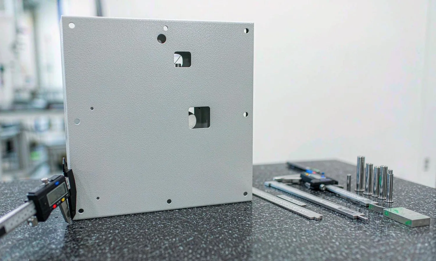
Start With a General Tolerance Note
The cheapest and most professional way to control tolerances on a sheet metal drawing is a general note, plus a small number of flagged critical dimensions. A typical general note covers:
- Cut and formed linear dimensions: ISO 2768-m or DIN 6935 style general tolerances
- Angles: ±0.5 degree unless stated
- Unspecified radii: inside radius 1.0 t unless stated
- Edge condition: deburred, sharp edges removed
- Surface: free from scratches on visible faces
Then flag the few dimensions your product genuinely depends on. A typical cabinet has three: the panel opening size, the mounting-hole pattern, and the overall height. Everything else can live with a general note.
Cutting Tolerances
| Feature | Typical achievable | Requires |
|---|---|---|
| Profile dimension (laser) | ±0.1 mm | Standard |
| Profile dimension (laser, thick material) | ±0.2 mm | Above roughly 6 mm |
| Hole position (laser) | ±0.1 mm | Standard |
| Hole diameter | ±0.1 mm, or ±5% for small holes | Standard |
| Punched hole position | ±0.15 mm | Standard on a turret punch |
| Hole diameter tolerance below ±0.05 mm | Needs reaming or secondary machining | Adds a separate operation |
| Kerf width tolerance | ±0.05 mm | Standard, but rarely a drawing requirement |
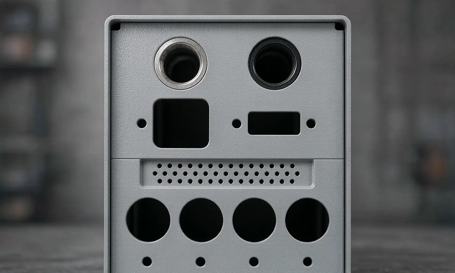
The message: laser cutting is inherently accurate. What adds cost is not tight profile tolerance - it is features outside the process window, such as holes smaller than the material thickness, sharp internal corners, extremely narrow tabs, and tolerances so tight that every part must be measured individually.
Bending and Forming Tolerances
| Feature | Typical achievable | Notes |
|---|---|---|
| Bend angle | ±0.5 degree | ±0.1 degree needs coining |
| Bend position | ±0.15 to ±0.3 mm | Worsens with part size |
| Overall formed dimension | ±0.3 to ±0.5 mm | Accumulates across bends |
| Flange height | ±0.3 mm | Also limited by minimum flange length |
| Twist / bow in a folded part | 0.5 mm per 500 mm approx. | Part size dependent |
Two practical points:
- Tolerance accumulates. Every bend adds a potential error. A box with six bends cannot hold ±0.1 mm overall, regardless of how good the press brake is.
- Critical dimensions are best taken after forming. Where a dimension must be exact - for example a mating panel opening - design for a trimming or machining operation after bending, rather than asking the bend to produce it.
Welding and Assembly Tolerances
This is where tolerances get expensive, because welding introduces heat and heat moves metal.
| Feature | Typical achievable | Notes |
|---|---|---|
| Welded assembly overall dimension | ±0.5 to ±1.5 mm | Depends on size and weld length |
| Squareness of a welded frame | 0.5 to 1 mm per 500 mm | Fixture quality dependent |
| Flatness after welding | 1 to 3 mm per metre | Worse on thin sheet |
| Door and panel gaps | ±0.5 mm visual target | Requires assembly check |
| Hole-to-hole across a welded assembly | ±0.5 mm | Accumulates from every joint |
If a welded assembly needs better than about ±0.5 mm across a large span, the design should carry adjustment features instead of demanding precision from a welding process - slotted mounting holes, an oversized cover, or a machined datum face added after welding.
Note · The single most cost-effective sentence you can add to a welded assembly drawing is: "provide slotted mounting holes for field adjustment unless otherwise specified". It converts a precision-welding problem into a design tolerance problem, at almost no cost.
How Tolerance Stacks Up
Every dimension in a chain contributes. If four bends each carry ±0.3 mm and three welded joints each carry ±0.5 mm, the worst-case accumulated error across the assembly is:
- Bends: 4 x ±0.3 mm = ±1.2 mm
- Welds: 3 x ±0.5 mm = ±1.5 mm
- Worst case total: ±2.7 mm
In reality errors do not always align in the same direction - statistical stack-up gives a smaller figure, roughly the square root of the sum of squares. But you cannot rely on statistics when one part must fit on a customer's bench. The practical rule: if your product needs ±0.5 mm at the end of a long chain, put the precision at the end of the chain, not at the start. Cut or machine the mating feature after assembly.
A Note on GD&T
Geometric dimensioning and tolerancing is a precise language, and it is genuinely useful for features like hole patterns, flatness and perpendicularity. Two cautions for sheet metal:
- Many GD&T callouts are unachievable after forming. A flatness of 0.1 mm on a 1.5 mm laser-cut and welded panel is not a manufacturing reality; it is a drawing exercise.
- Datum selection matters more than the values. Choose datums on features that are actually created accurately - a laser-cut edge or a machined face - not on a folded flange that carries its own tolerance.
If a design carries heavy GD&T, expect the supplier to raise the specific callouts that cannot be met by sheet metal processes. A supplier that quotes without comment is one that will not check.
Tolerance Checklist for Your Next Drawing
- Is there a general tolerance note covering everything unspecified?
- Are the two or three critical dimensions clearly flagged?
- Is any tolerance tighter than the process can hold without a secondary operation - and is that intentional?
- Are holes at least 1 t from bends and spaced at least 1.5 t from each other?
- Are internal corners rounded?
- For welded assemblies, is there an adjustment feature rather than a precision demand?
- Is the thickness tolerance basis stated? Actual thickness can sit below nominal.
- Is the flatness or straightness requirement stated as a number if it matters?
- Does the drawing state the deburring and edge condition?
- Is there a finish specification with colour, gloss and film thickness?
A drawing that answers these ten questions can be quoted accurately by any competent factory, compared fairly between suppliers, and manufactured without a mid-project argument.
Frequently Asked Questions
Typically ±0.1 mm on profile dimensions and hole positions for material up to moderate thickness, loosening to around ±0.2 mm on thicker material. Very fine features and holes smaller than material thickness are the real limit, not the general tolerance.
±0.5 degree is standard on a CNC press brake. Tighter than that requires coining, which increases cycle time and cost, and is rarely needed for enclosures.
Because welding introduces heat and each joint adds its own variation. Welded assemblies typically hold ±0.5 to ±1.5 mm overall. For tighter fits, add slotted holes or a machined datum rather than asking the welding process for more precision.
Use it selectively. Datum selection and hole-pattern position are genuinely useful. Flatness or perpendicularity tighter than about 0.2 mm per 100 mm generally cannot be produced by forming and welding alone, so those callouts should be negotiated rather than specified.
Write a general tolerance note for everything, then flag only the two or three dimensions your product truly depends on. Every extra tight tolerance adds inspection time, slowing production and raising price without improving the product.
Explore Related Capabilities
- Precision Sheet Metal Parts — Tight-tolerance laser cut and formed parts
- Control Panel Enclosures — Cut-out accuracy for PLC and HMI mounting
Have a Drawing to Quote?
Send STEP, DXF or PDF drawings and we reply with engineering feedback and a detailed quotation within 24 hours on working days.