Data Centre Cabinet Structure: Frames, Load Ratings and Seismic Bracing
Data Centre Anjue Metal | Data Centre | 12 min read | Updated Oct 12, 2026
A data centre cabinet is a structural element before it is an enclosure. It carries a load that may be measured in hundreds of kilograms, it sits in a row where a lean cannot be tolerated, and in many regions it has to survive a seismic event without opening or toppling. None of those are sheet metal details, but all of them are decided in the sheet metal design.
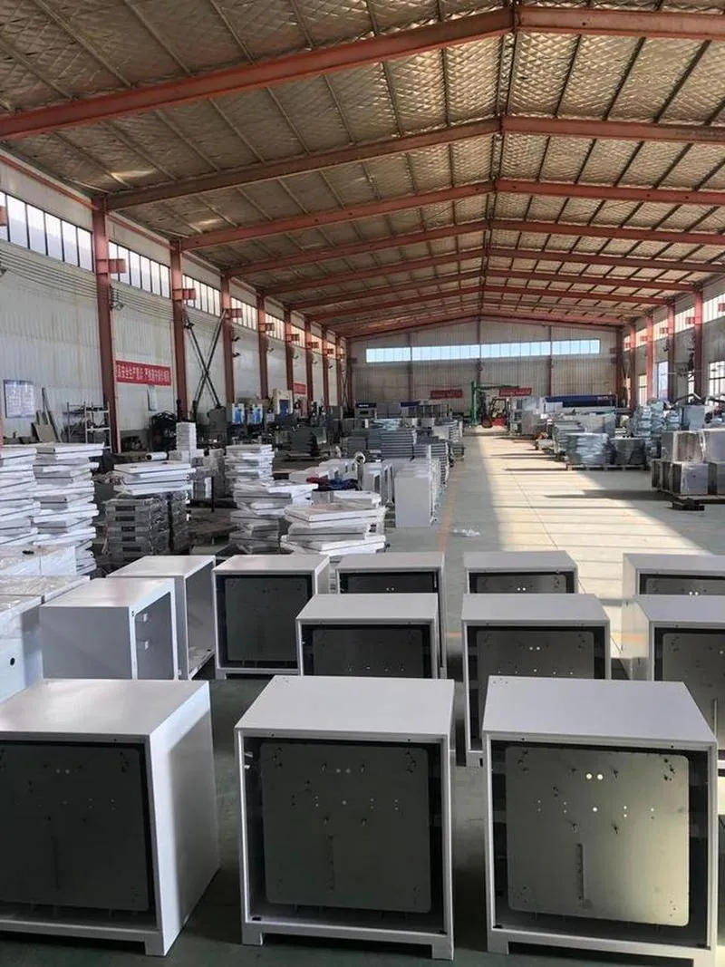
Load Cases You Should State
A cabinet brief that says "heavy duty" tells the fabricator nothing. State the load cases instead.
| Load case | What it describes | What it drives |
|---|---|---|
| Static distributed | Uniform mass through the cabinet | Frame section and rail support |
| Static concentrated | Mass concentrated high or at one side | Local stiffening and bracing |
| Installation transient | Sliding equipment on rails | Rail fixings and frame torsion |
| Door and access | Load applied to doors and panels | Hinge and latch specification |
| Seismic | Ground motion transferred through anchors | Frame, bracing, baying, anchors |
| Transport | Loads during shipping and handling | Packing and handling points |
Specifying the cases, rather than a single number, is what allows the frame to be designed rather than over-built.
Frame Stiffness and Section Choice
Stiffness comes from the geometry of the section and from how the corners are closed.
- Closed box sections in the vertical posts resist torsion far better than open sections of the same mass.
- Corner gussets and plates close the load path where the posts meet the top and base.
- Cross bracing is the most mass-efficient way to resist racking in an open frame.
- Base frames should carry the load into the fixing points rather than relying on the panels.
- Welded construction gives a stiffer, squarer frame than a bolted one, at the cost of shipping volume.
The design target is a frame that stays square under the worst load case, because rails, doors and baying all depend on squareness.
Rails, Depth and Adjustment
- Provide front and rear rails with a range of adjustment that covers the equipment you expect.
- Mark the depth positions, because unmarked rails are repositioned by trial and error.
- Use a positive lock rather than friction, so a loaded rail cannot creep.
- Keep the 19-inch hole pattern consistent front and rear, and agree the unit numbering convention.
- Allow for cable management depth behind the rear rail when setting the adjustment range.
Bracing, Baying and Row Stability
A cabinet is rarely installed alone, and the row is the real structure.
- Bay the cabinets with defined fixing points between adjacent frames, so the row acts as one stiff body.
- Use a common plinth where the floor requires it, so that levelling is shared rather than per cabinet.
- Brace the end cabinets of a row, since the ends carry the greatest racking load.
- Tie the row to the structure where the specification requires it, rather than relying on floor friction.
- Keep the baying face flat, because two cabinets that do not meet cleanly cannot be bolted into one line.
Floor Fixing, Plinths and Anchors
- Decide whether the cabinet sits on levelling feet, a plinth or a castor base, and design the base accordingly.
- Provide fixing holes at four corners as a minimum, with positions shown on the drawing.
- Consider a raised-floor interface where the cabinet spans a tile grid, so the load is transferred to the structure rather than to the tile.
- Keep the anchor specification with the cabinet specification, because a braced cabinet on an unspecified anchor is unverified.
- Where castors are used, put a defined parking or levelling arrangement under the load points.
Structural Interfaces with Containment
Structural design and airflow containment meet at the front and rear of the cabinet.
- Provide a flat, defined mounting face for containment doors and blanking panels.
- Keep the mounting features away from the frame's stiffening elements so both can exist.
- Allow for the roof aperture of a fan unit or a containment interface without cutting on site.
- Blanking panels are an airflow device, so the cabinet should make them easy to fit and keep in place.
How the Structure Is Verified
| Verification | Method | When |
|---|---|---|
| Frame squareness | Diagonal measurement | First article |
| Static load | Loaded rack test where required | First article or type test |
| Dynamic behaviour | Analysis or independent test | Where a seismic requirement exists |
| Fixing arrangement | Comparison with the anchor specification | At design review |
| Row alignment | Trial bay of two cabinets | First article |
| Door and panel fit | Open and close under load | First article |
Verification is cheapest before production, which is why the load cases belong in the brief rather than in a later conversation.
A Structural Brief That Gets Results
1. Load cases, including the concentrated case and any seismic requirement. 2. Floor type, fixing method and anchor specification. 3. Whether the cabinets will be bayed, and the baying interface. 4. Equipment depths and the cable management depth behind the rails. 5. Containment and airflow interfaces at the front and rear. 6. Volumes and whether a type test is required.
Our Approach to Cabinet Structure
- We fabricate welded and folded frames, plinths, base frames, gussets and bracing, and the baying interfaces between cabinets.
- We dimension the rail patterns, fixing points and baying features from a single datum so that a row assembles straight.
- We will tell you when a requested load case cannot be met by the proposed frame section and fixing arrangement.
- We do not perform seismic certification testing and we do not supply the anchors; those are specified and certified by the project engineer and an independent test house.
- Every quotation states which operations are completed in our plant.
Send the load cases, the floor conditions and the row layout, and the cabinet can be designed as a structural component rather than a box with rails in it.
Frequently Asked Questions
It means the frame will support that mass under a defined set of conditions, which almost always includes an evenly distributed load and a specified fixing arrangement. A cabinet rated at a high static load but only fixed at the front behaves very differently from the same cabinet bolted at four corners. The rating should be read together with the installation condition, and where the load will be concentrated, the concentrated case should be stated explicitly.
Because equipment is rolled in and out, doors are pushed, and in some regions the cabinet has to survive ground movement. Static capacity says the frame will hold a mass that never moves; dynamic requirements are about stiffness and about the fixings that resist a load that does. Two cabinets with the same static rating can behave completely differently when the load is moving.
It is the combination of frame stiffness, corner reinforcement, inter-cabinet baying and floor fixing that keeps the cabinet upright and closed during an event. It is normally certified as a system rather than as a part, which means the frame, the bracing, the anchor and the floor all have to be considered together. A stiff cabinet on a weak fixing is not a braced cabinet.
Enough to cover the range of equipment depths you expect and the depth of the cable management behind it. Adjustable rails, front and rear, with a marked scale, are far more useful than a fixed position, because equipment depths change over the life of the cabinet. The adjustment mechanism should lock positively; a rail that shifts under load is a hazard.
By designing the cabinet to be bayed. The side profiles, the fixing points between cabinets and the plinth or levelling arrangement should allow a row to be joined into one rigid line. Levelling feet alone will not hold a row straight, and a row that is out of line is difficult to close and unpleasant to service.
Explore Related Capabilities
- Network & Server Cabinets — Server and network cabinet structures
- Cabinet Frames & Structural Parts — Frames, plinths and braces
Have a Drawing to Quote?
Send STEP, DXF or PDF drawings and we reply with engineering feedback and a detailed quotation within 24 hours on working days.