1U to 4U Rack Chassis Fabrication: Dimensions, Panels and Structure
Rack and Chassis Anjue Metal | Data Centre | 12 min read | Updated Oct 12, 2026
A rack chassis is a box that has to line up with a standard it did not write. The mounting holes, the panel height and the slide rails are all fixed by an international pattern, and every design decision has to be made inside those constraints. This guide covers what is fixed, what is free, and where a fabricated chassis most often goes wrong.
- The Dimensions That Are Not Negotiable
- Units, Pitches and the Hole Pattern
- Chassis Formats and What Each One Suits
- Structure: Folded Body, Frame or Mixed
- Front Panels and I/O Openings
- Slide Rails and the Mounting Interface
- Materials, Thickness and Stiffness
- Finish, Appearance and Labelling
- First-Article Checks for a Rack Chassis
- Our Approach to Rack Chassis Fabrication
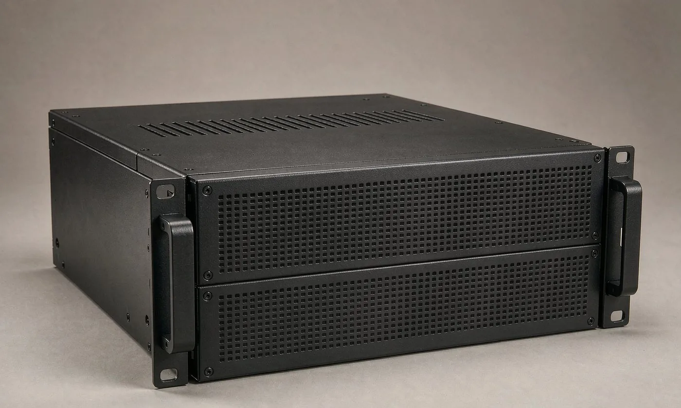
The Dimensions That Are Not Negotiable
A rack chassis is designed backwards from the rack. Three numbers are effectively given to you before the design starts.
| Dimension | Value | Who sets it |
|---|---|---|
| Rack unit pitch | 44.45 mm (1.75 in) per U | The rack standard |
| Mounting width | 482.6 mm (19 in) across the flanges | The rack standard |
| Mounting hole centres | 465.1 mm apart horizontally | The rack standard |
| Body width | 440 to 445 mm typical | The designer, inside the clearance |
Everything else, depth, internal layout, venting and finish, is a design decision. The mistake to avoid is treating the three fixed numbers as approximate; they are the interface with equipment the buyer already owns.
Units, Pitches and the Hole Pattern
Within each rack unit the rails carry a repeated hole pattern rather than a single hole. The universal pattern spaces three holes per U so that both wide and narrow equipment can be fixed, and the small offsets between them are what allow a chassis to be mounted either way up without redesigning the flange.
- Measure the flange holes from the agreed datum, not from a formed edge that carries bending tolerance.
- Keep the flange flat. A flange that pulls during welding or bending will not sit against the rail face.
- Allow for the thickness of the cage nuts or fixing hardware when setting the front panel stand-off.
- State which hole pattern is required if the buyer is using a non-universal rail.
Chassis Formats and What Each One Suits
| Format | Typical use | Practical note |
|---|---|---|
| 1U to 2U | Network appliances, patch panels, dense servers | Very little vertical room, so airflow dominates the layout |
| 3U to 4U | Storage, GPU servers, lab instruments | Enough height for a card cage and a mid-plane |
| Standard depth | Most cabinets and fixed rails | Cheapest and most common |
| Extended depth | Long cards and rear cabling | Check the rack depth before committing |
| Half-rack or quarter-rack | Lab and test equipment | Width compatibility with the rails must be checked separately |
Format decides the internal architecture. A 1U chassis has almost no height to work with, so the vent path is nearly forced. A 4U chassis has room to separate the power, the logic and the airflow, and the design should use it.
Structure: Folded Body, Frame or Mixed
There is no single correct construction, and the choice follows the loading and the volume.
- Folded body. Cheapest and fastest at low volume. Good stiffness comes from the folds themselves, and the body is essentially a folded box with a top cover.
- Folded body with internal bulkheads. Adds local stiffness where a card cage or a heavy power supply is mounted.
- Welded frame plus skins. Best for large or heavy units where a folded box would flex. Costs more, but the frame gives a rigid reference for the rails and the card guides.
- Extruded side walls. Common on aluminium chassis and useful when the side wall itself is a heat sink or a rail.
For a fabricated steel chassis, the practical rule is that stiffness should come from geometry rather than from thickness. A return or a bulkhead adds far more rigidity per kilogram than a heavier sheet.
Front Panels and I/O Openings
The front panel is the visible interface and the one part of the chassis that a customer will judge immediately.
- Opening geometry is the critical tolerance, because it sets where the drives, the fibre ports or the fascia sit.
- Rear I/O openings should be grouped and dimensioned from the same datum as the flange, so a purchased connector bracket drops in without filing.
- Vent apertures double as a design statement and as the primary air path; their size is a trade-off between airflow and shielding, which is covered in the companion guide on cooling and EMI.
- Earthing points and bonding studs belong on the drawing, not on a phone call.
Where a panel carries a printed overlay, leave a defined flat area and a registration feature, and agree the overlay thickness so the recess depth is right the first time.
Slide Rails and the Mounting Interface
A chassis that fits the rack but not the rails is still a failed chassis.
- Confirm the rail fixing method: front flange only, front and rear flange, or a side-mount intermediate rail.
- Confirm the rear fixing position, because rack depths and rail brackets vary between brands.
- Leave clearance behind the flange for the rail bracket and for the cable bend radius.
- Where the unit is heavy, provide a defined lifting or support point rather than relying on the flanges alone.
Materials, Thickness and Stiffness
| Requirement | Common choice | Reason |
|---|---|---|
| General enclosure | Cold-rolled steel, 0.8 to 1.2 mm | Stiff, cheap, takes paint well |
| Lightweight chassis | Aluminium, 1.0 to 2.0 mm | Weight and heat conduction |
| Shielding-critical | Steel or zinc-coated steel | Continuous conductive path |
| Corrosion-prone or hygienic | Stainless 304 or 316L | Cleanability and corrosion |
| High-usage sliding surfaces | Plated or coated steel | Wear and appearance |
Thickness follows the span between supports, not habit. A short, well-braced panel in thin sheet can be stiffer than a long unsupported panel in heavy sheet, and it will be lighter and cheaper.
Finish, Appearance and Labelling
- Powder coating is the default for painted steel chassis, with a defined texture and colour for the fascia area.
- Zinc or zinc-nickel plating is used where the chassis needs conductivity as well as corrosion protection.
- Bare or passivated aluminium suits extruded and machined chassis, and is often chosen for heat dissipation.
- Labelling and engraving should be planned with the finish, because laser marking on powder coat removes the coat whereas marking on bare metal does not.
First-Article Checks for a Rack Chassis
| Check | Method | Why |
|---|---|---|
| Flange hole pattern | Gauge or CMM against the standard | It is the rack interface |
| Front opening | Measured against the interface drawing | Fascia alignment |
| Overall width across flanges | Measured | Must pass between the rails |
| Flatness of flanges | Straight edge | A bowed flange will not seat |
| Rear I/O positions | Gauge | Purchased brackets must drop in |
| Slide rail fit | Trial fit on a rail set | The real test |
| Bonding continuity | Continuity check | Shielding depends on it |
The first article is where a chassis family is proven, and a family that is proven once is far cheaper to repeat than one that is corrected at every order.
Our Approach to Rack Chassis Fabrication
- We fabricate chassis bodies, covers, front panels and rear I/O panels in steel, aluminium and stainless.
- We dimension the flange holes and front openings from the standard and agree the datum on the drawing before cutting the flat pattern.
- We will flag a layout that cannot meet both the airflow requirement and the shielding requirement, rather than discovering it at the first thermal test.
- We do not supply the boards, power supplies, fans or slide rails, and we do not certify the electrical performance of the equipment.
- Every quotation states which operations are completed in our plant.
Send the rack standard, the rail details and the interface drawing, and the chassis can be dimensioned so that the first article fits the first time.
Frequently Asked Questions
One rack unit, or 1U, is 44.45 mm (1.75 in) of vertical pitch in the rack. A unit described as 2U occupies twice that pitch, 4U four times it. The pitch is fixed by the rack standard, so a chassis that is dimensioned in U is really being dimensioned against the mounting rail positions rather than against an arbitrary height.
The 19 in (482.6 mm) figure is the overall width across the mounting flanges, not the width of the body. Because the chassis has to pass between the rails, a real body usually finishes 440 to 445 mm wide, with the flanges taking up the difference. The front panel has to cover the full opening without fouling the rails, which is one of the details that separates a chassis that slides in easily from one that has to be forced.
No, and this is where most of the design freedom sits. Depth is set by the rack and by the equipment inside it, and adjustable rails mean the same chassis family can be offered in several depths. The constraints are the internal clearance for the boards and cabling, the slide rail length and the service access at the rear.
The mounting flange hole pattern and the front opening geometry. If the flange holes are off, the unit will not bolt into the rack; if the front opening is off, the fascia will not sit straight against its neighbours. Body tolerances can generally be looser, because the body sits inside the rack rather than against other units.
The rails, cage nuts and screws are normally buyer-supplied or sourced to the buyer's preferred brand, because they are a system choice rather than a sheet metal one. What we control is the mounting interface: the flange position, the hole pattern, the clearance behind the flange and the position of any rail-support features.
Explore Related Capabilities
- Rack & Data Centre Enclosures — Chassis, cabinets and rack parts
- 19" Rack Chassis & Cases — Server, network and audio enclosures
Have a Drawing to Quote?
Send STEP, DXF or PDF drawings and we reply with engineering feedback and a detailed quotation within 24 hours on working days.